Since I bought my house a year ago, which has a built-in garage with a radio controlled garage door opener, I have played with the idea that some day I will learn the basics of radio and replicate the signal from my garage door key fob and open the garage door from a command line.
This article explains step by step how I managed to figure that out. I have attempted to keep it strictly to the point and without involving too much detail. Interested readers are instead referred to the sources where I have found the information myself. Impatient readers can skip the next section, background, without losing context.
Background
Let me be frank. Before this project, I knew basically nothing about the technical aspects of radio. The topic always fascinated me, but never enough to actually start studying or examining how it works. It was first when I saw a YouTube video featuring a talk by the creator of rfcat which was held at the DEF CON ® 20 conference in 2012 that I became dedicated to learning the basics.
There are a few guides available online about these type of projects already (i.e. hacking fixed key remotes), but I couldn’t find one detailed enough for my scenario and simple enough for someone with my limited background in radio t0 understand. Before starting this project, my knowledge of radio was fairly limited to knowing how I could operate the radio in my car, that radio operates over different frequencies in the spectrum (radio broadcast, WLAN, RC etc) and that the data can be modulated in different ways (AM/FM) . I had no practical knowledge whatsoever and barely knew what pulse code modulation (ASK/OOK) was.
However, that didn’t stop me from learning how it could be done, and I combined the information I found online with additional support from two individuals on the #rfcat IRC channel on Freenode, AndrewMac and samy^^, who pretty much taught me everything I needed to know. AndrewMac had written an article on the topic a few years back, and samy^^ demonstrated a neat trick to me on how to decode wave patterns, which I will show you later on.
Gear
The gear I used to accomplish this project is listed below. All but the proprietary key fob can easily be ordered online.
- Software Defined Radio (SDR) that you can buy off Deal Extreme for $20
- TI CC1111 radio transceiver development kit, flashed with rfcat firmware (which allows it to operate in lower frequency ranges)
- GoodFET JTAG adapter (you need this to flash the firmware on the TI CC1111)
- Proprietary key fob that you want to replicate
Software
The guide assumes that the reader is using a Linux based operating system. If not, there are other alternative applications you can use (e.g. sdrsharp instead of gqrx), and you can probably, with a little effort, apply the remaining steps to suit your environment. If you’re running on a Linux based OS, you need three different applications to finish this project.
Gqrx
From the official README, Gqrx is an (experimental) software defined radio application implemented using GNU Radio and the Qt GUI toolkit. It works on Linux and Mac OSX. We will use this application to identify the signal from the key fob and make a recording of it.
rfcat
rfcat, similar to GNU cat, is aiming to be a standard utility to read or write the contents on the radio frequency spectrum. The main goals of the project are to reduce the time for security researchers to create needed tools for analyzing unknown (rf based) targets, to aid in reverse-engineering of hardware, and to satiate the developer’s rf lust. We will use this tool to replay the data we will decode from the key fob.
Audacity
Audacity is a free (both as in free beer and freedom), easy-to-use, multi-track audio editor and recorder for Windows, Mac OS X, GNU/Linux and other operating systems. In addition to playing audio, you can also use audacity to analyze wave patterns (e.g. transform a wave into a bit stream), which we will do later in this guide.
Flashing the CC1111EMK with custom firmware
As mentioned on the CC1111EMK product specification from Texas Instruments, it is designed to operate in the 868 MHz and 915 MHz frequency bands. The CC1111 SoC is however capable of operating in the following ranges, given that it has been flashed with the correct firmware:
- 300 – 348MHz
- 391 – 464MHz
- 782 – 928MHz
For additional details on the capabilities of the CC1111 chip, check out this information from the rfcat developers.
To flash the CC1111 with custom firmware, you also need a JTAG adapter like a GoodFET.
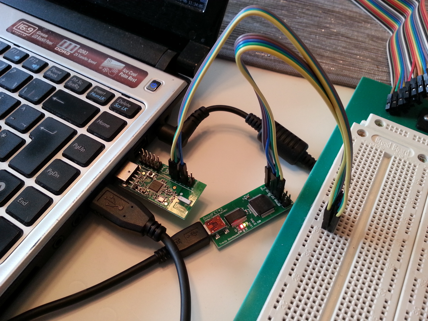
Once you have all the gear, connect the JTAG adapter to the CC1111 debug pins as per the rfcat documentation and as shown in the above image (I only had male-female connectors, so I had to use a breadboard in between).
EMK Dongle Details
           --------------------------------
           | 2 4 6 8 10   2 4 6 8 10      |
           | 1 3 5 7 9    1 3 5 7 9
           |-TEST-PINS----DEBUG-PINS------|
           |                              |
      ------                              |
      | USB                               |
      ------                              |
           | Don's Dongle (EMK)           |
           --------------------------------

              GoodFET              EMK
                PIN             DEBUG PIN

                 1 <----- DD -----> 4
                 2 <----- VCC ----> 2
                 5 <----- RST ----> 7
                 7 <----- DC -----> 3
                 9 <----- GND ----> 1
Once you have the connectors terminated, follow the remaining instructions in the rfcat documentation:
- Install sdcc
- Install make
- Make sure both are in the path
- cd into the “rfcat/firmware/” directory
- “make testgoodfet” will read info from your dongle using the GoodFET. You should see something like this:
SmartRF not found for this chip.
Ident CC1111/r1103/ps0x0400
Freq 0.000 MHz
RSSI 00 - “make backupdongle” will read the current firmware from your dongle to the file …/bins/original-dongle-hex.backup.
(“make restoredongle”) to revert to the original firmware. - “make clean installRfCatDonsDongle” will clean, build, and install the RfCat (appFHSSNIC.c) firmware for a cc1111emk.
Once you have finished flashing the CC1111EMK, we continue by capturing the signal from the proprietary key fob.
Capturing the signal
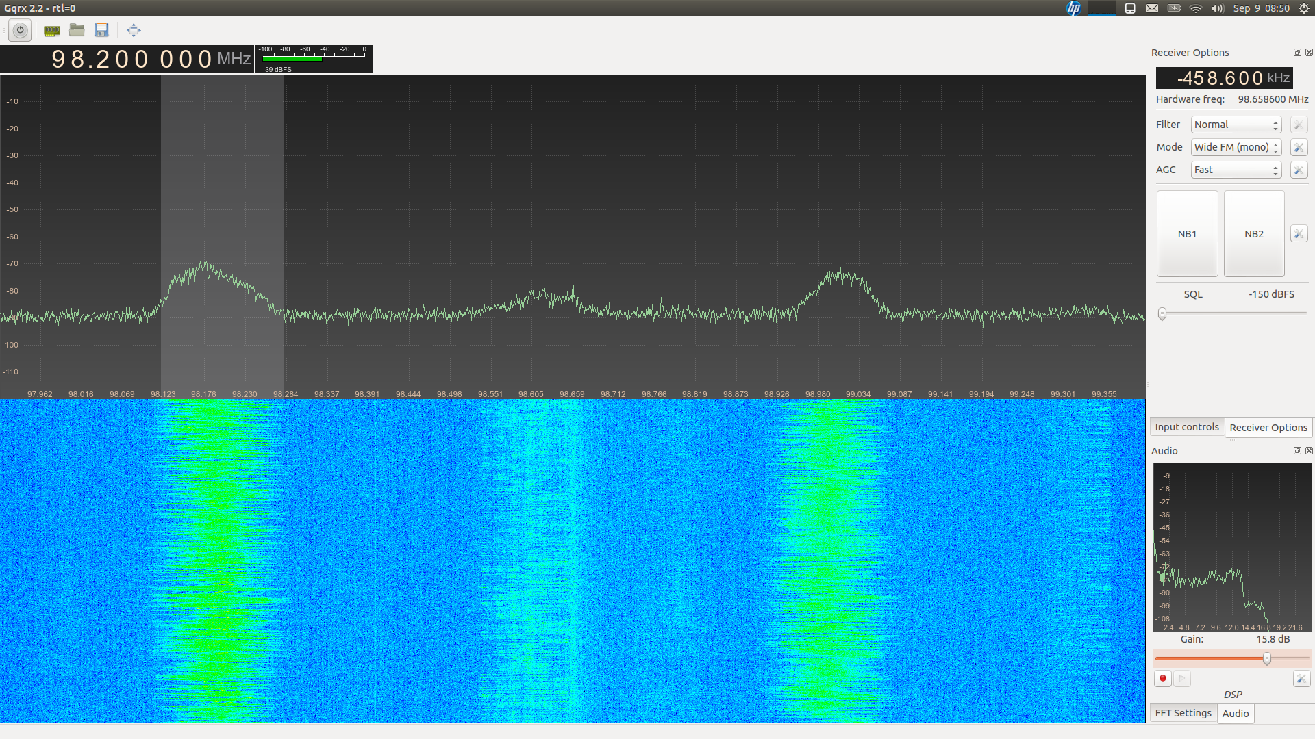
Capturing the signal requires that you can listen to the rf spectrum in gqrx, so you need to connect your SDR to a USB socket and ensure you have the correct drivers installed. After that, you can activate the SDR from the power button in gqrx, and it will look something like the below screenshot (which has nothing to do with this project). The screenshot below displays two strong wide FM radio signals, where one is operating on the 98.200 MHz frequency.
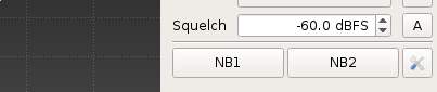
To make a recording of the signal from your key fob, you need to know which frequency it is operating on. Most of these garage door key fobs operate somewhere around 433 MHz (mine was set to 433.92 MHz, and it was even printed on the remote). Once you have discovered the frequency, try to squelch the background noise as much as possible to get a clean signal. This is done by adjusting the squelch parameter, as shown in the below screenshot. As my SDR’s antenna was quite close to the keyfob, -60 dBFS turned out great.
Once you have made a recording, you can look at the result in Audacity.
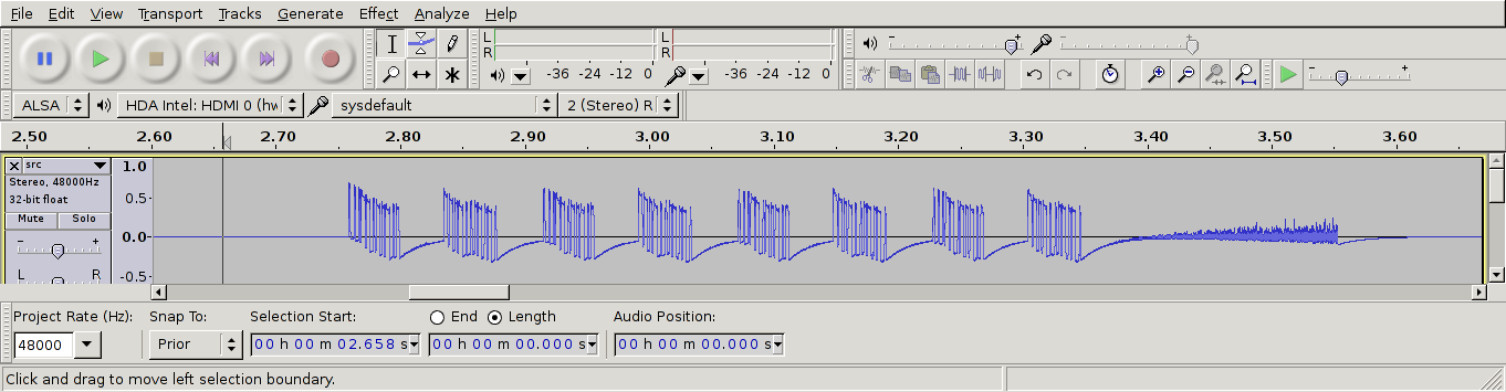
We are only interested in the data between 2.75ms and 3.35 ms. The pattern after 3.35 ms is simply noise from the transmitter. As we can see from the recording, there are 8 data groups (or “packets”). The next step now is to further analyse these blocks and ultimately decode it.
Decoding the signal
Decoding the signal can be done in several ways. My first attempt was to use the rtl_433 application which allowed me to make a data dump of the signal (as interpreted by rtl_433), as shown from the output below. However, I had no way of verifying whether it was correct or not except for the fact that 8 packets were sent.
As we can see from the output, rtl_433 reports that
- The keyfob sends 8 packets, of which 2 are unique (i.e. 2 alternating packets, sent four times)
- Packet 1 consists of the bitstream 00011010 10000000 (0x1a, 0x80)
- Packet 2 consists of the bitstream 11010001 01000000 (0xd1, 0x40)
I suspected that the decoded bitstream was incorrect, as the last part of all the eight packets (alternating between 10000000 and 01000000) didn’t resemble the waveform previously displayed.
The image below shows the first of eight packets that are transmitted from the key fob. As seen, there are two types of pulses that are sent – short and long. The packet starts with three short pulses, followed by two long etc. If we compare this with the output of rtl_433, the first eight bits (00011010) matches the pattern where short pulses are interpreted as 0 and long pulses as 1 – but the second byte (10000000) is way off.
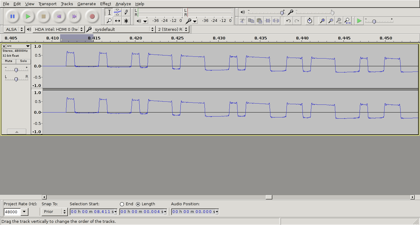
This might have happened due to incorrect configuration parameters in rtl_433 when I made a dump of the data. If you look closely, you’ll notice that the packet doesn’t even contain 16 pulses, which would be required to decode the data to two bytes with this method, but merely twelve!
At this point, I started asking more experienced people on IRC for input on how to decode the 12 pulses, and I eventually got in contact with samy^^ on the #rfcat channel on Freenode, who suggested not to count each pulse as a bit, but consider each pulse, which lasts ~4ms, as 4 bits! This is essentially the same as setting the baud rate to 1000 Bd.
Since Audacity has the possibility to highlight data down to 1 ms, this made the process a whole lot easier. I have made a GIF below to illustrate this. Note that I no longer count short pulses as 0 and long pulses as 1, but every 1 ms as either 0 or 1, depending on whether the carrier (i.e. when the amplitude is high) is present or not.
Using this trick, the following 6 bytes can be extracted from this waveform:
- 00010001
- 00010111
- 01110001
- 01110011
- 01110001
- 00110000
After I had used this method to decode the first packet, I repeated the process for the second packet. Since the whole bit stream consisted of sending packets 1 and 2 repeatedly 4 times, we are now done with the decoding stage and can continue with replaying the data.
Replaying the signal
For replaying the signal, we use the rfcat library which is available here. The library is written in Python, and it is quite simple to get started using it. The official documentation (i.e. the README file which is part of the project) is quite good, but fails to mention signal strength and how you disable sending the default preamble.
To use rfcat, you can either use the rfcat script, which is basically a wrapper to either Python or IPython (whichever is available) that imports all the libraries you need – or you can create a script yourself in case you need to do something a bit more advanced. The below screenshot shows the “welcome” screen when you fire up the rfcat script.
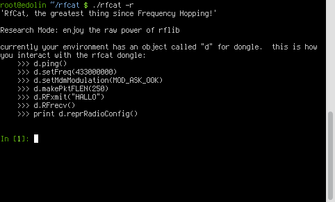
Two interesting methods that are not mentioned in the welcome screen, are:
- d.setMdmSyncMode(0) – By default a preamble or sync word is sent before the user data. The keyfob used in this guide did not make use of a preamble, so we disable it.
- d.setMaxPower() – By default the CC1111EMK with rfcat firmware transmits the signal with low power. If you run this method, it will set the power to the maximum which would make your signal travel longer.
Finally, the following code is my end result which allowed me to open my garage door from a CC1111EMK using rfcat and rfcat firmware.
#!/usr/bin/python2.7

import time
import sys
from rflib import *

FREQ = 433920000 # Set my frequency to the gate remote
PKTLEN = 6       # Set my packet length to 6 as I am sending
                 # 6 bytes in each packet
DRATE = 1000     # baud rate of 1000 means that a 1ms pulse
                 # can be counted as a bit

packet_1 = [
            '00010001', '00010111', '01110001',
            '01110011', '01110001', '00110000'
           ]
packet_2 = [
            '00010001', '00100100', '01100111',
            '01001010', '00001111', '00011110'
           ]
data_hex_1 = [ chr(int(x, 2)) for x in packet_1]
data_hex_2 = [ chr(int(x, 2)) for x in packet_2]

def send_data(d, data, repeat=4):
    # PCM'ify the packets
    for i in range(0,repeat):
        for packet in data:
            d.RFxmit(packet)
try:
    d = RfCat()
    d.setFreq(FREQ)
    d.setMdmModulation(MOD_ASK_OOK)
    d.makePktFLEN(PKTLEN)
    d.setMdmDRate(DRATE)
    d.setMdmSyncMode(0) # disable syncword and preamble as this is not used
                        # by the remote.
    #d.setMaxPower()    #imma chargin' mah lazer
    send_data(d, ["".join(data_hex_1), "".join(data_hex_2)])

except Exception, e:
    sys.exit("Error %s" % str(e))
    # TODO implement software reset in case of USB timeout
If you are interested in more information regarding RF signals and use of rfcat, I recommend reading:
